H05RN-F 300/400 V
Heavy-duty H05RN-F harmonized cable built with robust rubber insulation and flexible copper conductors for demanding industrial and outdoor applications. Its excellent resistance to oil, water, abrasion and weathering makes it ideal for portable power supplies, construction sites, pumps, generators and mobile equipment. Designed under European harmonized standards for superior flexibility and durability.
Generally Conforms to, DIN VDE 0282 PART 810, IEC 245, BS7655,BS7919/ HD22.1, HD22.4
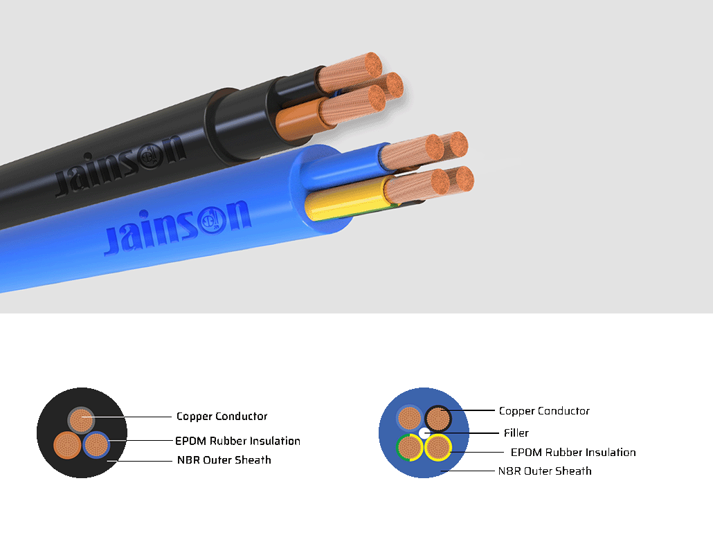
Conductor : Flexible Class 5 copper conductor according to DIN VDE 0295,IEC 60228*Any other Color on specific request can also be supplied
- JAINSON H05RN-F rubber insulated and sheathed cables are intended for flexible connection to electrical equipment. They are suitable for both indoor and outdoor use in industrial and agricultural plant and on construction sites.
- Coils 100 and 200 m in carton boxes, reels
Dimensions of type 60245 IEC 53
|
Number and nominal cross-sectional area of conductors mm² |
Thickness of insulation Specified value mm |
Thickness of sheath Specified value mm |
Mean overall diameter Lower limit mm |
Mean overall diameter Upper limit mm |
| 2 x 0,75 | 0,6 | 0,8 | 5,7 | 7,4 |
| 2 x 1 | 0,6 | 0,9 | 6,1 | 8,0 |
| 2 x 1,5 | 0,8 | 1,0 | 7,6 | 9,8 |
| 2 x 2,5 | 0,9 | 1,1 | 9,0 | 11,6 |
| 3 x 0,75 | 0,6 | 0,9 | 6,2 | 8,1 |
| 3 x 1 | 0,6 | 0,9 | 6,5 | 8,5 |
| 3 x 1,5 | 0,8 | 1,0 | 8,0 | 10,4 |
| 3 x 2,5 | 0,9 | 1,1 | 9,6 | 12,4 |
| 4 x 0,75 | 0,6 | 0,9 | 6,8 | 8,8 |
| 4 x 1 | 0,6 | 0,9 | 7,1 | 9,3 |
| 4 x 1,5 | 0,8 | 1,1 | 9,0 | 11,6 |
| 4 x 2,5 | 0,9 | 1,2 | 10,7 | 13,8 |
| 5 x 0,75 | 0,6 | 1,0 | 7,6 | 9,9 |
| 5 x 1 | 0,6 | 1,0 | 8,0 | 10,3 |
| 5 x 1,5 | 0,8 | 1,1 | 9,8 | 12,7 |
| 5 x 2,5 | 0,9 | 1,3 | 11,9 | 15,3 |
NOTE: The mean overall dimensions have been calculated in accordance with IEC 60719.
Note
- The number of wires is approximate and wire diameter is nominal; they shall be such as to satisfy the requirements of conductor resistance of IEC 60245 / DIN VDE 0295 / IS 8130 / BS 6360 or UL83