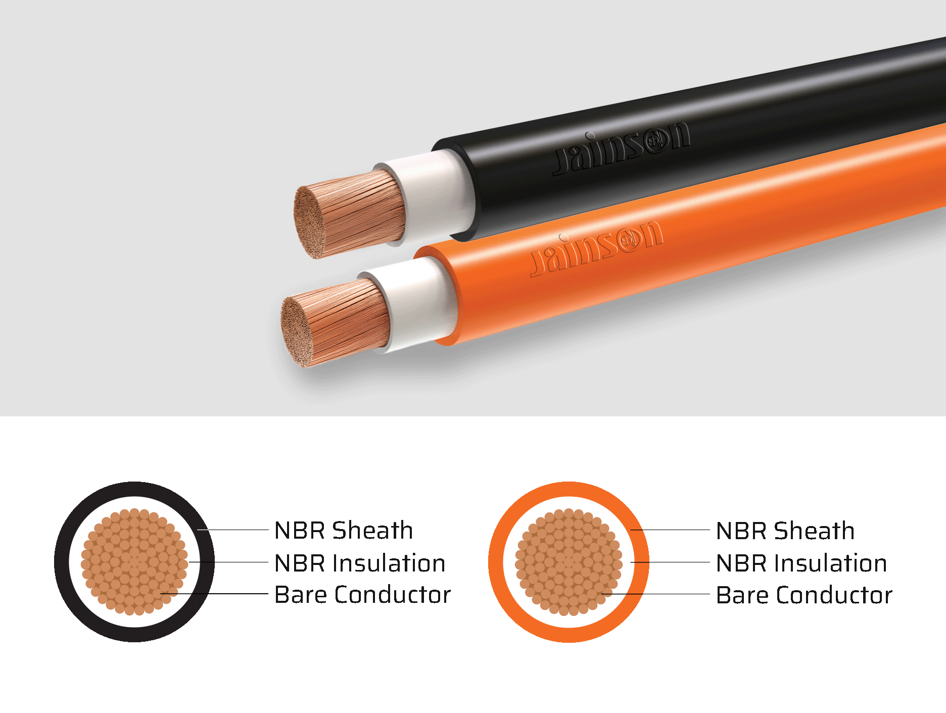
NBR Double Insulated Extra Flexible Copper Welding Cable
A high-performance welding cable featuring ultra-flexible, fine-stranded copper conductors with robust double NBR insulation, designed for demanding welding environments. Its superior flexibility and flame-retardant properties ensure reliable performance under constant movement, rugged conditions, and thermal stress. With excellent resistance to abrasion, oil, chemicals, ozone and weathering this cable is ideal for industrial and workshop welding applications.
Elongation = 300 Min.
- Designed for the secondary (high current) connection to automatic or hand – held metal arc welding electrodes. It is suitable for flexible use under rugged conditions, on assembly lines and conveyor systems, in machine tool and automatically operated line and spot welding machines.
- Coils 100, 200, 300 and 500 m. in wooden reels
The maximum current ratings of flexible welding cables for different duly cycles are based on an ambient air temperature of 25°c and a maximum conductor temperature of 90°c. The percentage duly cycles for various processes and applications are as follows:
- Automobile Welding : up to 100%
- Semi-automatic Welding : 30% to 85%
- Manual Welding : 0% to 60%
- Very intermittent or Occasional Welding : up to 20%
When total cable lengths in excess of 15 mtrs., are involved, it may be necessary to use cables of larger cross section to ensure that the voltage drop is not excessive and welding currents are maintained at adequate levels.
TECHNICAL INFORMATION
| Cross Sectional Area | Copper Construction | Inner Dia | Outer Dia Appx. | Max. Conductor Resistance at 20˚C | Current Rating | Non Welding Application | ||||
|---|---|---|---|---|---|---|---|---|---|---|
| Welding Application | ||||||||||
| Duty Cycle | ||||||||||
| 100% | 85% | 60% | 30% | 20% | ||||||
| Sq. mm. | Nos. / Dia. mm | mm | mm | Ω/km | amp | amp | amp | amp | amp | amp |
| 10 | 322 / 0.20 | 6.30 | 9.90 | 1.910 | 105 | 115 | 135 | 190 | 235 | 110 |
| 16 | 511 / 0.20 | 8.00 | 10.70 | 1.210 | 135 | 145 | 175 | 245 | 302 | 138 |
| 25 | 798 / 0.20 | 9.50 | 12.10 | 0.780 | 180 | 195 | 230 | 330 | 402 | 187 |
| 35 | 1121 / 0.20 | 11.00 | 14.20 | 0.554 | 225 | 245 | 290 | 410 | 503 | 233 |
| 50 | 1596 / 0.20 | 12.30 | 16.30 | 0.386 | 285 | 310 | 370 | 520 | 637 | 295 |
| 70 | 2220 / 0.20 | 14.40 | 18.70 | 0.272 | 355 | 385 | 460 | 650 | 794 | 372 |
| 95 | 1349 / 0.30 | 16.60 | 20.80 | 0.206 | 430 | 470 | 560 | 790 | 961 | 449 |
| 120 | 608 / 0.50 | 18.20 | 23.00 | 0.161 | 500 | 540 | 650 | 910 | 1118 | 523 |
| 150 | 760 / 0.50 | 21.10 | 27.60 | 0.129 | 580 | 620 | 740 | 1040 | 1297 | 608 |
| 185 | 943 / 0.50 | 23.80 | 30.80 | 0.106 | 660 | 715 | 850 | 1200 | 1476 | 690 |
| 240 | 1225 / 0.50 | 26.80 | 34.00 | 0.0801 | 710 | 770 | 916 | 1296 | 1587 | 744 |
| 300 | 1498 / 0.50 | 30.30 | 37.50 | 0.0641 | 800 | 850 | 1035 | 1450 | 1790 | 840 |
| 400 | 2035 / 0.50 | 33.60 | 41.30 | 0.0486 | 925 | 1000 | 1195 | 1690 | 2070 | 970 |
Note
The number of wires is approximate and wire diameter is nominal; they shall be such as to satisfy the requirements of conductor resistance of IEC 60228 / DIN VDE 0295 / IS 8130 / BS 6360
In view of continuous improvements in our design and process, specifications given here in are subject change without notice.
> All are flexible conductor
> Insulation material is NBR
> Sheath material is NBR
| Ambient temperature °C | 20° | 25° | 30° | 35° | 40° | 45° | 50° | 55° | 60° | 65° |
| Rating Factor | 1.04 | 1.00 | 0.96 | 0.91 | 0.87 | 0.82 | 0.76 | 0.69 | 0.64 | 0.57 |