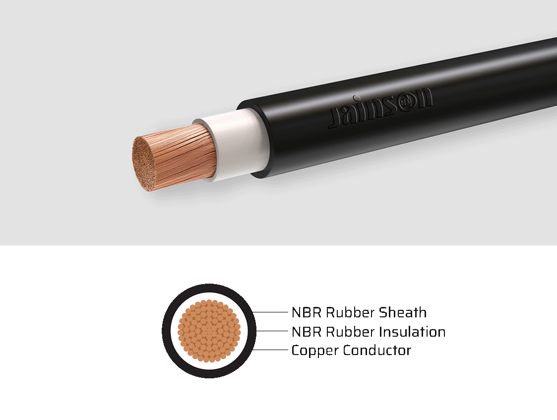
NBR DOUBLE INSULATED EXTRA FLEXIBLE COPPER WELDING CABLE (AWG SIZE)
This extra-flex NBR welding cable features fine-stranded copper conductors and flexible insulation for smooth handling and robust performance in welding applications. Its excellent resistance to environmental and mechanical stresses ensures durability and long-term reliability. Ideal for connections between welding machines and electrode holders in industrial and fabrication settings.
Elongation = 300 Min.
- Coils 100, 200, 300 and 500 m. in wooden reels
TECHNICAL INFORMATION
| Cross Sectional Area | Copper Construction | Nominal Thickness | Outer Dia Appx. | Max. Conductor Resistance at 20˚C | Max. Current (Amb. Temp of 40˚C) |
|---|---|---|---|---|---|
| AWG | Nos. / Dia. mm | mm | mm | Ω/km | AMPS |
| 6 | 273 / 0.254 | 8.00 | 10.70 | 1.39 | 115 |
| 4 | 427 / 0.254 | 9.50 | 12.10 | 0.873 | 150 |
| 2 | 651 / 0.254 | 11.00 | 14.20 | 0.554 | 205 |
| 1 | 817 / 0.254 | 11.70 | 15.40 | 0.44 | 240 |
| 1/0 | 1045 / 0.254 | 12.30 | 16.30 | 0.349 | 285 |
| 2/0 | 1330 / 0.254 | 14.40 | 18.70 | 0.276 | 325 |
| 3/0 | 1672 / 0.254 | 16.60 | 20.80 | 0.221 | 380 |
| 4/0 | 2146 / 0.254 | 18.20 | 23.00 | 0.175 | 440 |
| 250MCM | 2508 / 0.254 | 21.10 | 27.60 | 0.149 | 495 |
| 350MCM | 3496 / 0.254 | 20.80 | 30.80 | 0.106 | 680 |
| 500MCM | 5013 / 0.254 | 26.80 | 34.00 | 0.0743 | 720 |
Note
The number of wires is approximate and wire diameter is nominal; they shall be such as to satisfy the requirements of conductor resistance of IEC 60228 / DIN VDE 0295 / IS 8130 / BS 6360
In view of continuous improvements in our design and process, specifications given here in are subject change without notice.
> All are flexible conductor
> Insulation material is NBR
> Sheath material is NBR
| AMPS | 100˚ | 150˚ | 200˚ | 250˚ | 300˚ | 350˚ | 400˚ |
|---|---|---|---|---|---|---|---|
| 100 | 4 | 4 | 2 | 2 | 1 | 1/0 | 1/0 |
| 150 | 4 | 2 | 1 | 1/0 | 2/0 | 3/0 | 3/0 |
| 200 | 2 | 1 | 1/0 | 2/0 | 3/0 | 4/0 | 4/0 |
| 250 | 1 | 1/0 | 2/0 | 3/0 | 4/0 | ||
| 300 | 1/0 | 2/0 | 3/0 | 4/0 | |||
| 350 | 1/0 | 3/0 | 4/0 | ||||
| 400 | 2/0 | 3/0 | |||||
| 450 | 2/0 | 4/0 | |||||
| 500 | 3/0 | 4/0 | |||||
| 550 | 3/0 | 4/0 | |||||
| 600 | 4/0 |