EPM/LSZH 0.6/1Kv 90°C
Safety-oriented single core cable combining EPM insulation with a low smoke zero halogen (LSZH) outer sheath for enhanced fire safety and reduced toxic emissions. Built for flexibility and robust performance up to 90 °C, it resists abrasion, mechanical stress and environmental factors while maintaining superior electrical properties. Ideal for power supply, telecom systems, marine and shipboard use where safety and low smoke emissions are critical.
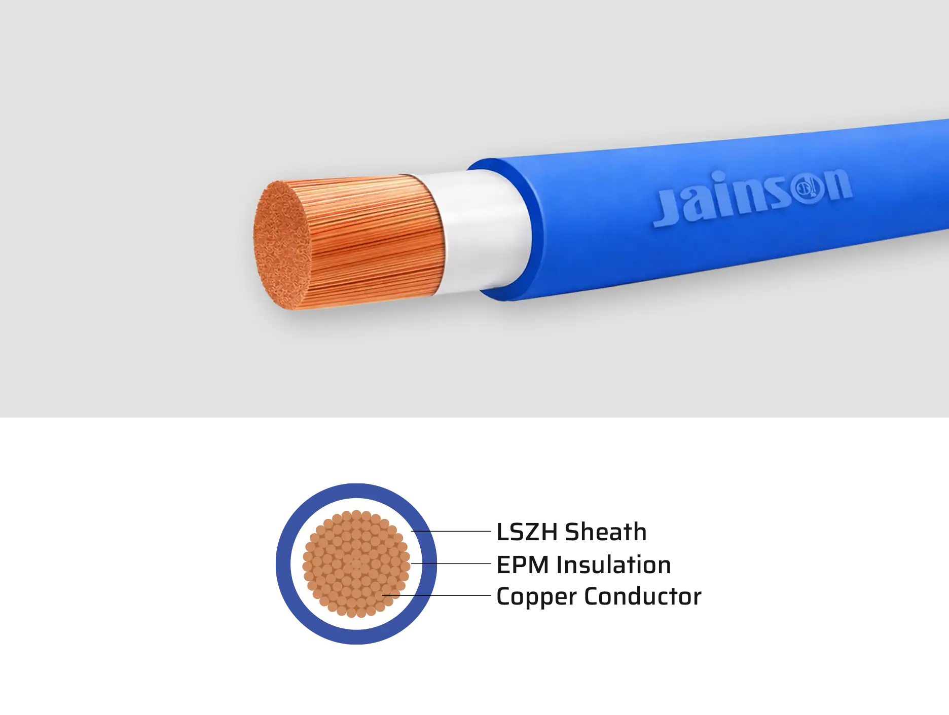
Cable Structure
Conductor : EC
copper class 5 and class 6 generally conforms to IEC 60228, DIN VDE 0281
Insulation :
EPM
Sheath : LSZH (Low
Smoke Zero Halogen) Gray, Orange, Black, Red, Blue
*Any other Color on specific request can also be supplied
Technical Data
Fixed installation :
-20°c to max.+90°C
Nominal Voltage :
1100 V
Test Voltage : 3000
V
Insulation
resistance : Min. 10 MΩ x km
Min. bending radius
: 6 x Cable Diameter
Flame propagation :
Flame retardant test as per IEC 60332-1
Application
EPM/LSZH 0.6/1Kv
90°C
- Suitable for D.C. power supplies on Telecom equipment and power applications where flexibility is required
Shipboard and offshore marine use where a low smoke halogen free tinned flexible cable is required for safety and to meet Certification Society approvals
- Suitable for D.C. power supplies on Telecom equipment and power applications where flexibility is required
Shipboard and offshore marine use where a low smoke halogen free tinned flexible cable is required for safety and to meet Certification Society approvals
Standard length cable
packing:
- Coils 100, 200,300 and 500 m in wooden reels
- Coils 100, 200,300 and 500 m in wooden reels
Cable Features
Zero halogen low smoke insulation
Ultra high performance flexible for longer life and added safety
High flame retardant properties
Outstanding toughness & durability
High resistance to cuts, tears & abrasion
Resistance to oil, solvents and chemicals
Excellent ozone and weather resistant
Technical DataTable - EPM/LSZH single core double insulated cable
| Cross Sectional Area | Copper Construction | Inner Dia. | Outer Dia Appx. | Max. Conductor Resistance at 20˚C |
| Sq. mm. | Nos. / Dia. mm | mm | mm | Ω/km |
| 10 | 322 / 0.20 | 6.30 | 9.90 | 1.910 |
| 16 | 511 / 0.20 | 8.00 | 10.70 | 1.210 |
| 25 | 798 / 0.20 | 9.50 | 12.10 | 0.780 |
| 35 | 1121 / 0.20 | 11.00 | 14.20 | 0.554 |
| 50 | 1596 / 0.20 | 12.30 | 16.30 | 0.386 |
| 70 | 2220 / 0.20 | 14.40 | 18.70 | 0.272 |
| 95 | 1349 / 0.30 | 16.60 | 20.80 | 0.206 |
| 120 | 608 / 0.50 | 18.20 | 23.00 | 0.161 |
| 150 | 760 / 0.50 | 21.10 | 27.60 | 0.129 |
| 185 | 943 / 0.50 | 23.80 | 30.80 | 0.106 |
| 240 | 1225 / 0.50 | 26.80 | 34.00 | 0.0801 |
| 300 | 1498 / 0.50 | 30.30 | 37.50 | 0.0641 |
| 400 | 2035 / 0.50 | 33.60 | 41.30 | 0.0486 |
- The number of wires is approximate and wire diameter is nominal; they shall be such as to satisfy the requirements of conductor resistance of IEC 60228 / DIN VDE 0295 / IS 8130 / BS 6360
- In view of continuous improvements in our design and process, specifications given here in are subject change without notice.
All are flexible conductor
Insulation material is EPM
Sheath material is LSZH
