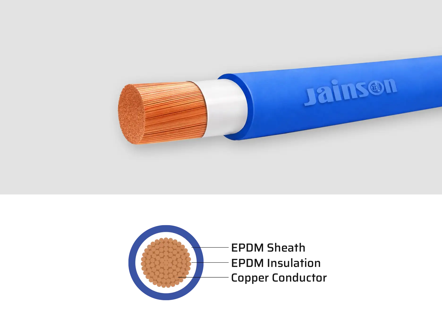
EPDM/EPDM 0.6/1Kv 110°C
Versatile single core double insulated cable with both insulation and sheath made from EPDM rubber for outstanding elasticity, heat resistance and mechanical toughness. Rated for continuous operation up to 110 °C, it delivers reliable flexibility and enhanced resistance to cuts, abrasion, oils and weathering. Perfect choice for flexible power connections, switchgear, load banks, transformers and submersible wiring across industrial and commercial installations.
Generally confirming to IEC 60228, IEC60502-1, AS/NZ500:2003 & AS/NZS60079, CE Directive 72/23/EEC.
*Any other Color on specific request can also be supplied
- For applications where extreme flexibility is required - high current capacity. Power - Switchboards, flexible droppers from busbars, transformers, load banks or other equipment requiring fixed or flexible wiring. Pumping - Suitable for permanent submersionn
- Coils 100, 200,300 and 500 m. in wooden reels
Technical DataTable - EPDM/EPDM single core double insulated cable
| Cross Sectional Area | Copper Construction | Inner Dia. | Outer Dia Appx. | Max. Conductor Resistance at 20˚C |
| Sq. mm. | Nos. / Dia. mm | mm | mm | Ω/km |
| 10 | 322 / 0.20 | 6.30 | 9.90 | 1.910 |
| 16 | 511 / 0.20 | 8.00 | 10.70 | 1.210 |
| 25 | 798 / 0.20 | 9.50 | 12.10 | 0.780 |
| 35 | 1121 / 0.20 | 11.00 | 14.20 | 0.554 |
| 50 | 1596 / 0.20 | 12.30 | 16.30 | 0.386 |
| 70 | 2220 / 0.20 | 14.40 | 18.70 | 0.272 |
| 95 | 1349 / 0.30 | 16.60 | 20.80 | 0.206 |
| 120 | 608 / 0.50 | 18.20 | 23.00 | 0.161 |
| 150 | 760 / 0.50 | 21.10 | 27.60 | 0.129 |
| 185 | 943 / 0.50 | 23.80 | 30.80 | 0.106 |
| 240 | 1225 / 0.50 | 26.80 | 34.00 | 0.0801 |
| 300 | 1498 / 0.50 | 30.30 | 37.50 | 0.0641 |
| 400 | 2035 / 0.50 | 33.60 | 41.30 | 0.0486 |
- The number of wires is approximate and wire diameter is nominal; they shall be such as to satisfy the requirements of conductor resistance of IEC 60228 / DIN VDE 0295 / IS 8130 / BS 6360
- In view of continuous improvements in our design and process, specifications given here in are subject change without notice.
